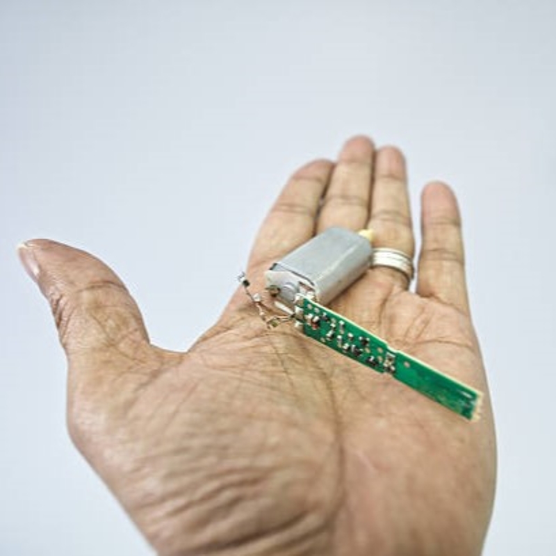

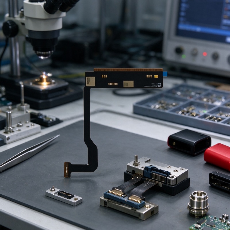
Compact electronic products require circuit boards that make efficient use of limited internal space while maintaining reliable electrical connections. In particular, flexible circuit structures allow designers to arrange components and routing paths around different enclosure shapes. An integrated e-cigarette FPC bare board combines a thin construction with flexible layout options, making it suitable for compact pod systems, disposable devices, and other electronic product designs. Therefore, selecting the right board structure and customization approach is important when developing space-conscious electronic assemblies.
How Does Flexible Layout Optimize Compact Circuit Designs?
Traditional rigid circuit layouts can limit component placement when an enclosure has a narrow or irregular internal structure. By contrast, flexible circuit boards allow designers to plan routing paths around available spaces and accommodate different assembly requirements. This flexibility can help reduce unnecessary layout restrictions while supporting more efficient use of the product enclosure. As a result, an integrated e-cigarette FPC bare board can provide a practical foundation for compact electronic designs that require customized circuit arrangements.
Flexible layouts also support different connection positions, pad locations, and component arrangements. For example, designers can adjust connector zones and coil layouts according to the available installation space. In addition, the board can be designed to accommodate bending or folding requirements where the application allows. These options make a flexible vape circuit board useful for projects that need a specific shape or connection arrangement rather than a standard board layout.
Why Are Material Selection and Thermal Stability Important?
Material selection influences the board’s mechanical properties, electrical performance, and suitability for assembly processes. The supplied product specification identifies poly as the base material and describes a design intended to withstand high-temperature soldering and mechanical stress. Moreover, the copper foil supports current conduction and signal routing, helping designers organize power and signal paths within a compact layout. Since the exact copper thickness is not specified in the supplied parameters, it should be confirmed during project evaluation.
The board design also supports applications where bending and folding are required. However, the acceptable bending conditions depend on the final layout, installation space, and mechanical requirements. Therefore, the design team should evaluate the intended bending areas before confirming the circuit structure. This step helps ensure that the board layout matches the product enclosure and assembly process.
What Technical Parameters Should Be Considered?
Before starting a custom project, buyers and engineering teams should review the main manufacturing parameters. These details help determine whether the board can meet the required layout, thickness, surface treatment, and assembly conditions. The following table summarizes the specifications provided for this product.
| Manufacturing Parameter | Specification |
|---|---|
| Layer | 1–4L |
| Base Material | Poly |
| Minimum Line Width | 0.05 mm / 2 mil |
| Minimum Line Spacing | 0.05 mm / 2 mil |
| Minimum Aperture | 0.1 mm (mechanical) |
| Copper Thickness | Not specified |
| Plate Thickness | 0.05–0.25 mm |
| Surface Treatment | Immersion Gold; OSP |
| Complete Copper | 1 OZ |
| Solder Resist Layer | Yellow, black, white |
| Test | Fixture test |
| Construction Time | 72H |
| Listed Standards and References | ISO9001:2015, ROHS, UL94V0, IPC-6012 standards |
These parameters provide a starting point for evaluating the board’s manufacturing requirements. For instance, the minimum line width and spacing help define routing possibilities, while the available surface treatments offer options for different assembly needs. Furthermore, the 0.05–0.25 mm plate thickness range gives designers a defined range to consider when planning the board structure.
How Does OEM Customization Support Different Product Designs?
A standard circuit layout may not meet every project’s internal space, connector position, or component arrangement requirements. For this reason, OEM customization is important when developing an electronic cigarette motherboard or a small-size e-cigarette PCB module. Designers can adjust custom pad positions, connector zones, and coil layouts according to the product’s mechanical structure. Consequently, the integrated e-cigarette FPC bare board can be developed around specific enclosure dimensions and connection requirements.
Customization can also involve surface treatment and solder mask selection. Immersion gold and OSP are the listed surface treatment options, while yellow, black, and white are available solder resist colors. In addition, SMT components can be arranged according to the board layout and assembly requirements. These choices help businesses coordinate electrical design, manufacturing processes, and product integration within one development plan.
A complete e-cigarette PCBA solution may also require coordination between bare board production and subsequent assembly. Therefore, it is useful to define the component layout, connector positions, board dimensions, and testing requirements before production begins. This approach can reduce unnecessary design changes and make communication between engineering and manufacturing teams more efficient.
How Do Manufacturing and Quality Checks Support Consistency?
Manufacturing quality depends on both process control and inspection. The supplied process information includes AOI inspection, electrical testing, and reliability simulations to help evaluate board quality. Additionally, fixture testing provides a defined test method for checking the manufactured boards. Together, these procedures support production consistency and help identify potential manufacturing issues before delivery.
Packaging and delivery preparation are also important considerations. Panelized delivery can support organized handling during production, while vacuum packaging helps protect boards from oxidation and contamination during storage and transportation. Moreover, the stated construction time is 72H, which provides a reference for project planning. Actual schedules should still be confirmed according to the final design, order quantity, and manufacturing requirements.
When evaluating a manufacturing partner, businesses can review several important points:
- Layout customization: Confirm whether pad positions, connector zones, and circuit routing can match the product design.
- Material and thickness: Check the base material and plate thickness against the required enclosure and assembly conditions.
- Surface treatment: Select immersion gold or OSP according to the project’s manufacturing requirements.
- Inspection process: Review AOI inspection, electrical testing, and fixture testing arrangements.
- Delivery preparation: Confirm panelized delivery and vacuum packaging requirements.
Applications and Custom Development Opportunities
Flexible circuit boards are useful in compact electronic products where internal space and connection arrangements require careful planning. For pod systems and other compact electronic designs, a customized board layout can help organize components within the available enclosure. Similarly, projects that require curved or irregular internal spaces may benefit from flexible layout options. RIMYI provides customized FPC board development to support different layout and integration requirements.
For businesses developing a new product, the most effective approach is to define the enclosure dimensions, connection positions, component requirements, and production expectations early. This information allows the engineering team to evaluate the board structure before moving into manufacturing. Ultimately, an integrated e-cigarette FPC bare board should be developed around the actual product design, with material selection, circuit routing, and quality inspection considered together.
Conclusion
Flexible circuit layouts offer useful design options for compact electronic products that require efficient internal routing and customized component placement. By combining defined manufacturing parameters, multiple surface treatment options, flexible layout planning, and inspection procedures, businesses can develop boards that better match their product requirements. In addition, OEM customization helps coordinate the circuit design with enclosure dimensions and assembly needs. Careful planning with an experienced manufacturing partner can therefore support a more consistent development process from initial layout to production.