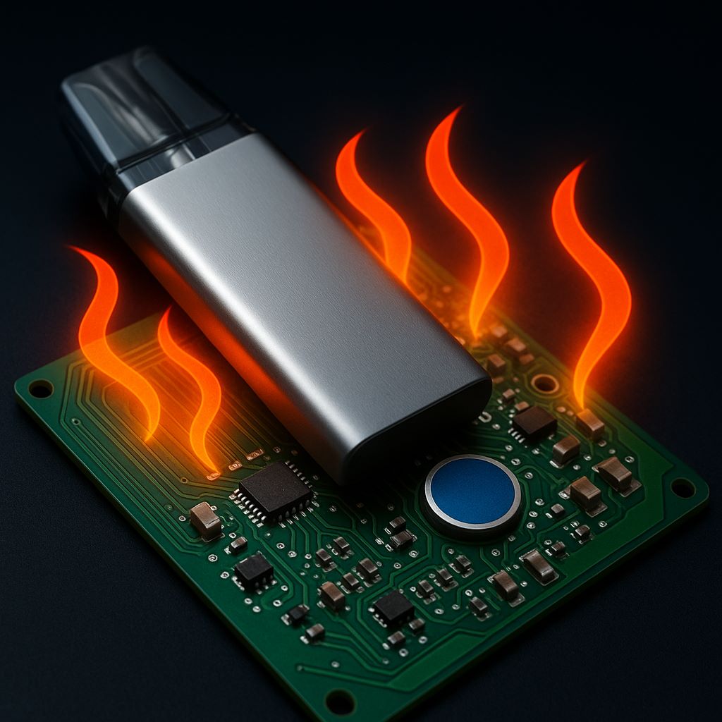
Why Heat Matters in Ultra-Slim Vape Boards
As vaping devices continue to shrink in size, the demand for ultra-slim vape mainboard designs has skyrocketed. Cependant, compactness introduces thermal challenges. Ineffective heat dissipation affects both safety and performance. In this context, thermal engineering becomes critical to sustain reliability, battery integrity, and component lifespan.
À Rimyi, we focus on providing precision PCB solutions for e-cigarette brands worldwide. Dans cet article, we examine the engineering methods to enhance thermal control while preserving slim profiles. We also explore how design evolution and materials science intersect to define next-generation vaping hardware.
01. The Thermal Constraints of Compact Vape Boards
Slim devices have minimal airflow and limited surface area. Par conséquent, heat becomes trapped inside the mainboard unit.
Challenges include:
-
High component density increases thermal load.
-
Thin PCB layers reduce thermal pathways.
-
Battery proximity raises temperature sensitivity.
-
Plastic enclosures hinder natural convection.
Although vaping hardware uses low-power components, le continuous operation of heating coils, sensors, and microcontrollers can gradually raise internal temperatures.
02. Sources of Heat in Vape Circuitry
Understanding heat sources is essential before applying design improvements. The most common include:
a) Power Regulation Circuits
These include buck/boost converters, MOSFETs, and voltage regulators. Even with high efficiency, energy loss turns into heat.
b) Battery Management Systems (BMS)
BMS units regulate charging and protect against overcurrent. When enclosed, they become localized heat zones.
c) Coil Drivers and Sensing Circuits
Heating coils demand stable current delivery. The switching circuits and temperature sensors near the coil contribute to localized heat buildup.
03. Heat Path Design in Slim Vape PCBs
In ultra-slim vape mainboards, there is no space for bulky heatsinks or fans. Instead, designers rely on PCB-level thermal optimization:
1. Copper Plane Utilization
Increase copper fill in inner and outer layers. Thicker copper (≥2oz) acts as a passive heat sink. Thermal vias connect hot layers to GND planes.
2. Spreading Heat through Ground Layers
Connect high-power components directly to the internal ground planes. This helps in evenly distributing heat across the board.
3. Thermal Vias and Pads
Placing arrays of small vias under hot chips transfers heat vertically. Use via stitching near MOSFETs or power inductors.
4. Component Spacing Strategy
Although space is tight, isolating thermally active components by a few millimeters prevents heat stacking.
5. Board Stack-up Optimization
Multilayer boards with thermal breaks between digital and analog sections reduce thermal coupling and improve regulation.
04. Material Selection for Thermal Performance
Choosing high-Tg, low-CTE base materials is vital for slim designs. Here are the recommended materials:
| Material | Features | Benefits of Vape PCB |
|---|---|---|
| FR-4 High Tg | Tg >170°C | Budget solution, stable under short bursts |
| Polyimide | Flexible & high heat resistance | Ideal for curved or non-planar PCBs |
| Metal-core PCB (MCPCB) | Aluminum or copper backing | Great for thermal paths from coil drivers |
| Ceramic Substrates | Excellent thermal conductivity | Costly, but effective for high-end vape modules |
RIMYI engineers match materials to client device profiles. Our labs test thermal behavior under real usage cycles.
05. Component Placement & PCB Layout Strategy
Thermal-aware placement is more than spacing. Key layout tactics include:
-
Locate hot ICs away from battery enclosures or edge walls.
-
Orient airflow paths through vents or slots, if possible.
-
Place temp-sensitive components in the coolest zones.
-
Avoid stacking heat-generating ICs near each other on multilayer PCBs.
06. Coating, Shielding & Encapsulation Impacts
Slim vape PCBs often require conformal coating or EMI shielding for compliance. Cependant, these can block heat escape.
Guidelines:
-
Use thin silicone coatings with thermal conductivity.
-
Avoid covering both sides of thermally active zones.
-
Use metal shielding cans with vented designs for RF circuits.
Proper selection ensures both safety and temperature control without performance tradeoffs.
07. Future Innovations in Vape PCB Thermal Design
The miniaturization trend will intensify. Thus, engineers must prepare for:
-
Graphene-infused coatings for better surface cooling.
-
Embedded microchannels in rigid-flex PCBs for liquid cooling.
-
System-on-substrate integration to shorten heat paths.
RIMYI is investing in these technologies, collaborating with materials suppliers and vape OEMs to deliver the next-gen cooling solutions.
Conclusion: Heat Management Enables Design Freedom
As devices become thinner, smarter, and more powerful, ultra-slim vape mainboard designs must tackle heat head-on.
Thermal design is no longer a secondary concern — it defines user safety, comfort, and product durability. With the right Disposition des PCB, materials, and simulation tools, brands can build ultra-slim vape devices that don’t compromise performance.
À Rimyi, we believe that great vaping hardware starts with great PCB design. Through collaborative engineering and precision manufacturing, we enable brands to bring reliable, thermally optimized, ultra-slim devices to market.


