The vaping industry continues to evolve with user demands for precise control, safety, and compact design. At the heart of this innovation lies the custom e-cigarette voltage module, a compact, powerful PCB assembly that regulates voltage delivery to the atomizer in box mods. Designing and integrating such modules requires engineering insight, PCB expertise, and attention to vaping dynamics.
Dans cet article, we share an in-depth guide on how to design and embed a custom voltage PCB into your box mod—balancing form, function, and thermal safety. This guide not only enhances product development efficiency but also helps brands build reliable, next-generation vape devices.
Understanding the Role of Voltage PCB Modules in Box Mods
Modern box mods rely on regulated voltage to deliver consistent vapor production. A voltage PCB module manages the electrical power flowing from the battery to the atomizer. This function is critical in preventing dry hits, overheating, or device damage.
A well-designed voltage module ensures:
-
Stable voltage output under variable load.
-
Battery protection and thermal cutoff.
-
Precision control via user interface (UI) or sensors.
-
Integration with display and feedback mechanisms.
To embed this system in a compact housing, a custom vape PCB integration approach must consider spatial constraints, battery specifications, and thermal dissipation requirements.
Core Design Objectives for a Custom Voltage PCB Module
Designing a box mod voltage module starts with defining performance expectations. These include output voltage range, battery type, resistance detection, safety limits, and control interface.
Define Output and Power Requirements
First, determine the voltage range required—commonly 3.3V to 8.4V in dual-cell mods. Calculate the expected current draw and wattage, based on resistance ranges (usually between 0.1Ω and 2.5Ω). The module must support real-time adjustments while keeping power delivery stable.
Establish Safety Parameters
Next, safety parameters must be embedded into the control logic. Include:
-
Overcurrent protection
-
Reverse polarity protection
-
Battery cutoff thresholds
-
Overheat auto-shutdown
By integrating temperature sensors and voltage comparators, the system actively monitors operating conditions.
Choose Control Logic & Microcontroller
The control core manages user input and regulates output voltage. Select a microcontroller unit (MCU) with PWM capability, ADC channels for battery monitoring, and SPI/I2C interfaces for display or Bluetooth control. Popular choices include STM32 or low-power Atmel MCUs.
To optimize space, the PCB can integrate passive components such as inductors, capacitors, and resistors in a single multilayer configuration.
PCB Layout Design for Compact Box Mod Integration
After establishing system logic, the physical layout determines performance and feasibility. A compact PCB requires smart routing, EMI shielding, and heat management.
Optimize Component Placement
Group high-frequency elements and power transistors near the battery input and output terminals. Minimize trace lengths between the MCU and FETs to reduce switching losses. Use differential pairs if implementing USB charging or communication.
Critical analog paths—like thermistor sensing or coil resistance detection—must be isolated from digital noise sources. Shielded zones improve signal fidelity.
Thermal Management Is Essential
Power regulation generates heat, especially during sub-ohm operation. The PCB must dissipate this heat effectively to prevent failure.
Use a thermal conductive substrate, such as an aluminum-core or copper-backed FR4 board, to conduct heat away from MOSFETs and inductors. Embed thermal vias beneath high-wattage components to direct heat to the bottom layer.
Apply heat-conductive pads or graphite foil between the PCB and mod casing to improve heat transfer.
Layer Stackup and Signal Integrity
Multilayer PCBs provide better routing and EMI shielding. A common 4-layer stack includes:
-
Top layer: power and signal
-
Inner layer 1: ground plane
-
Inner layer 2: power plane
-
Bottom layer: analog and control logic
This stack minimizes crosstalk and supports clean analog-to-digital conversion. Route digital and analog paths separately to reduce interference.
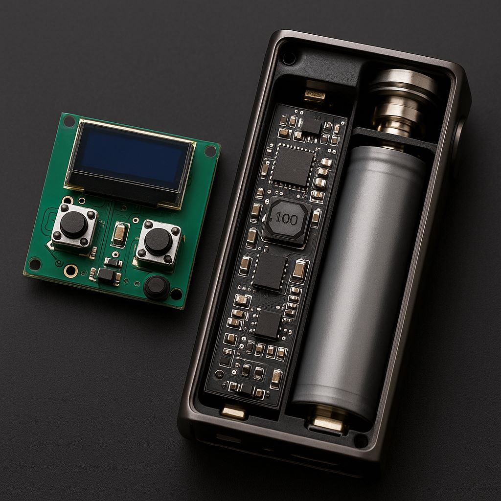
Embedded User Interface and Firmware Design
The module’s success also depends on how well the UI and firmware are implemented. Most custom e-cigarette voltage modules feature:
-
OLED or TFT screens
-
Button or touch interfaces
-
Bluetooth connectivity for remote control
The firmware interprets user input, manages voltage control loops, and displays relevant information such as wattage, battery level, and resistance.
Voltage Regulation Algorithm
Use either PWM or buck-boost control to regulate voltage. Implement PID or simpler control logic depending on hardware complexity. Feedback loops must be fast and accurate to prevent overshoot or delay during vaping.
Low-latency firmware ensures a smooth firing experience and fast protection response.
Battery Management and Charging Integration
Many modern box mods integrate USB-C charging and even pass-through vaping. This demands advanced battery management circuitry.
Include Charging IC and Protection
Use dedicated lithium-ion charging ICs like TP4056 or BQ24195, which provide:
-
CC/CV charging mode
-
Charge status indication
-
Thermistor-based temperature control
-
Short-circuit protection
Implement a power path management scheme to allow vaping during charging without affecting battery charging cycles.
Embedding the PCB Module into the Box Mod
Once validated, the module must be embedded into the module’s mechanical structure. PCB shape, mounting points, and connector types affect integration success.
Match Mechanical Housing
Design the PCB to fit seamlessly within the mod casing. Use 3D modeling to align connector ports, buttons, and screen placement. Make provisions for battery wiring and connector strain relief.
Include anchor holes and alignment notches for structural rigidity.
Secure Electrical Interfaces
Use JST or Molex connectors for battery and display modules. Apply conformal coating to protect against moisture. Where necessary, reinforce solder joints with epoxy for drop protection.
Avoid long flying wires, which increase EMI and reduce robustness.
Conclusion: Achieving Custom Vape PCB Integration Success
Designing and embedding a custom voltage PCB into your box mod requires technical precision and cross-domain expertise. The process spans electrical design, Disposition des PCB, thermal management, firmware programming, and mechanical integration.