

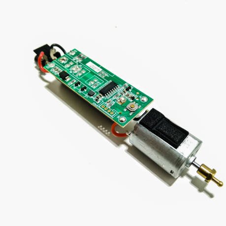
For e-cigarette brands and hardware engineers, battery capacity ( mAh ) is often the primary metric used to market device longevity. While a larger battery profile certainly extends active vaping time, it only addresses half of the user-experience equation. The true indicator of structural engineering quality—and the factor that determines whether a device survives on a retail shelf or inside a consumer’s pocket without dying—is its quiescent current.
Quiescent current is the baseline electrical current drawn from the battery when the device is completely idle but remains ready to wake up. In the competitive e-cigarette market, many basic setups suffer from high standby leakage. This causes hardware to completely drain its cell capacity within just a few weeks of non-use, leading to dead-on-arrival (DOA) retail stock and frustrating consumer returns.
By contrast, reducing this idle draw to a quiescent current threshold of <15μA transforms hardware shelf life, extending standby performance from weeks to months. This technical guide outlines the engineering strategies required to achieve ultra-low power efficiency in low-power vape PCB design.
1. The Standby Math: Quiescent Current vs. Real-World Lifespan
To visualize how microscopic micro-ampere μA fluctuations impact the commercial shelf-life of an e-cigarette, we can look at a mathematical model using a standard 500 mAh lithium-ion cell.
The ideal standby duration (T_standby) is calculated by dividing total battery capacity (C_battery) by the system’s quiescent leakage current (I_Q):
The matrix below shows how different current thresholds alter consumer satisfaction and hardware shelf reliability:
| Quiescent Current (IQ) | Standby Lifespan (500mAh Cell) | Market Viability & Experience |
| >50 μA (Unoptimized Basic PCB) | approx 416 Days (<1.1 Years) | Poor. High risk of self-discharge; stock frequently arrives dead at retail locations. |
| 15 μA to 20 μA (Standard Tier-1 Market Spec) | approx 1,141 Days (approx 3.1 Years) | Good. Dependable shelf-life; maintains structural battery health during transit. |
| <10 μA (Advanced Custom PCBA) | mathbf{>1,736 Days (>4.7 Years) | Elite. Excellent protection; minimal self-discharge across extended distribution cycles. |
2. Low-Power Engineering: How to Minimize Leakage Current
Achieving a stable <15 μA quiescent current requires careful hardware optimization across the entire PCBA layout. Engineers must implement a multi-layered power management strategy:
                      [Unoptimized Battery Source]
                                   │
       ┌───────────────────────────┼───────────────────────────┐
       ▼                           ▼                           ▼
 [Deep Sleep Firmware]    [Power Domain Isolation]    [Intermittent Sensor Polling]
 Forces MCU into stop     Disconnects voltage rails   Puts airflow sensors to sleep
 mode ($<2\mu\text{A}$).  to non-essential ICs.      except during a 50ms pulse.
A. MCU Sleep Mode Optimization
The main microcontroller unit (MCU) must not sit in a continuous run state when the user isn’t actively puffing. The system firmware must be structured to immediately drop the MCU into its lowest power domain, or deep sleep mode, within seconds of inactivity. In this deep sleep configuration, the core high-frequency clocks and main internal oscillators are shut down, dropping the MCU’s individual current draw down to a mere 1.5 to 3 μA.
B. Power Domain Isolation & Leakage Blocking
A common mistake in standard PCB layout is leaving secondary chips—such as LED drivers, display controllers, or fuel gauges—connected to the main battery voltage rail (V_BAT) while idle. Even when turned off via software, these peripheral integrated circuits (ICs) experience parasitic leakage current through their internal ESD protection diodes.
Advanced low-power vape PCB layouts fix this by implementing discrete, hardware-level load switches (MOSFETs). When the device enters its idle state, the MCU opens these gates, completely cutting power to non-essential hardware sub-systems and eliminating parasitic leakage.
C. Intermittent Sensor Polling Strategy
Modern e-cigarettes rely on automated mic sensors or pressure transducers to detect a user’s inhalation. If these sensors remain fully powered 100% of the time, they continuously draw anywhere from 30 μA to 100 μA.
To lower this footprint, the power distribution network uses a duty-cycled pulsing strategy. Instead of continuous monitoring, the system applies power to the sensor for a tiny 1-millisecond window every 50 milliseconds to check for pressure drops. This intermittent sampling cuts the sensor’s average energy usage by over 95% while keeping the system responsive.
3. The Design Trade-off: Deep Sleep vs. Light Sleep
When designing firmware for a low-power vape PCB, engineers must carefully balance low-power states against user-responsiveness:
| Architectural Metric | Light Sleep Mode Profile | Deep Sleep Mode Profile (PCBA Target) |
| Current Consumption | High (150μA to 500 μA ) | Ultra-Low (<5 μA Baseline Draw) |
| Internal Oscillator Status | High-frequency internal clocks remain active | Core clocks disabled; Low-power RTC active |
| Wake-Up Hardware Trigger | Any basic GPIO change or internal flag | Dedicated external interrupt pin (Puff Sensor) |
| Sensor Wake-Up Latency | Instantaneous (<5μs response) | Low-latency bridge delay ( approx 15 ms to 30 ms ) |
| Impact on Vape Experience | No noticeable puff delay | Immediate firing upon intake detection |
4. Keeping Essential Features Active During Deep Sleep
The ultimate test of an ultra-low-power vape mainboard is maintaining its safety features and user responsiveness while keeping standby current to an absolute minimum.
[Airflow Inhale Input] ──> [Hardware External Interrupt] ──> [Instant Core Clock Wake] ──> [Safe Atomization Output]
-
Always-On Airflow Monitoring: Even when the system is in deep sleep, the hardware interrupt lines connected to the pressure sensor must remain alert. The design maps the sensor’s analog trigger output directly to an external hardware interrupt pin on the MCU. The moment a user takes a puff, the physical air pressure change creates an analog voltage signal that bypasses software checks and immediately wakes the core processors.
-
Optimized Wake-Up Latency: If the MCU takes too long to wake up from deep sleep, the user will experience an uncomfortable lag between their inhale and actual vapor production. Advanced low-power firmware structures use fast-starting internal RC oscillators that can wake the entire device and fire the heating element within 20 milliseconds of an inhale detection. This ensures a responsive, instant-draw experience while preserving months of standby battery health.
Conclusion: Engineered for Maximum Shelf Reliability
In the fast-moving consumer electronics market, a product’s real-world reliability depends heavily on its baseline power efficiency.
Stop losing retail market share and customer loyalty to unoptimized mainboards that drain their batteries while sitting in storage. By upgrading your product line to an advanced low-power vape PCB framework that guarantees a stable <15μA quiescent current, you protect the health of your battery cells, maximize shelf-life, and ensure your devices deliver a reliable, instant puff every time.
Contact our engineering team today to review your hardware layout and build an optimized power management system tailored to your next product launch.